Structural Design Loads
Seismic Design Category & Site Class Explained (SDC A–F)
What the Seismic Design Category (A through F) is, what drives it, and why it shapes structural system choices, detailing, and cost from the earliest design stage.
On this page
Last updated August 14, 2026 · Concepts per ASCE 7 (Ch. 11) and IBC Section 1613; mapped acceleration parameters from the USGS Seismic Design Maps / ASCE Hazard Tool. Any values shown are illustrative and the official ASCE Hazard Tool + AHJ-adopted code govern. Official references: [ASCE Hazard Tool](https://ascehazardtool.org/); [ASCE/SEI 7-22](https://www.asce.org/publications-and-news/codes-and-standards/asce-sei-7-22); [2024 IBC Chapter 16](https://codes.iccsafe.org/content/IBC2024P1/chapter-16-structural-design); [2021 IBC Chapter 16](https://codes.iccsafe.org/content/IBC2021P2/chapter-16-structural-design); [FEMA P-2192-V1, 2020 NEHRP design examples](https://nibs.org/wp-content/uploads/2025/04/fema_nehrp_design-examples-and-training-materials_volume01.pdf); [FEMA P-2192-4, SDC maps for 2024 IRC and IBC](https://www.fema.gov/sites/default/files/documents/fema_p-2192-nehrp-provisions-seismic-design-maps-2024-irc-ibc.pdf); [UFC 3-301-01 nonstructural component design guide (ASCE 7-22)](https://nibs-s3-wbdg3-production.s3.us-east-1.amazonaws.com/FFC/DOD/UFC/UFC_3-301-01_NONSTRUCTURAL_COMPONENT_DESIGN_RC_I_TO_IV.pdf); [NCSEA ASCE 7-16 Irregularity Guide](https://www.ncsea.com/app/uploads/2024/02/Seismic-Guide.pdf); [USGS Design Ground Motions portal](https://www.usgs.gov/programs/earthquake-hazards/design-ground-motions-portal).
Direct answer
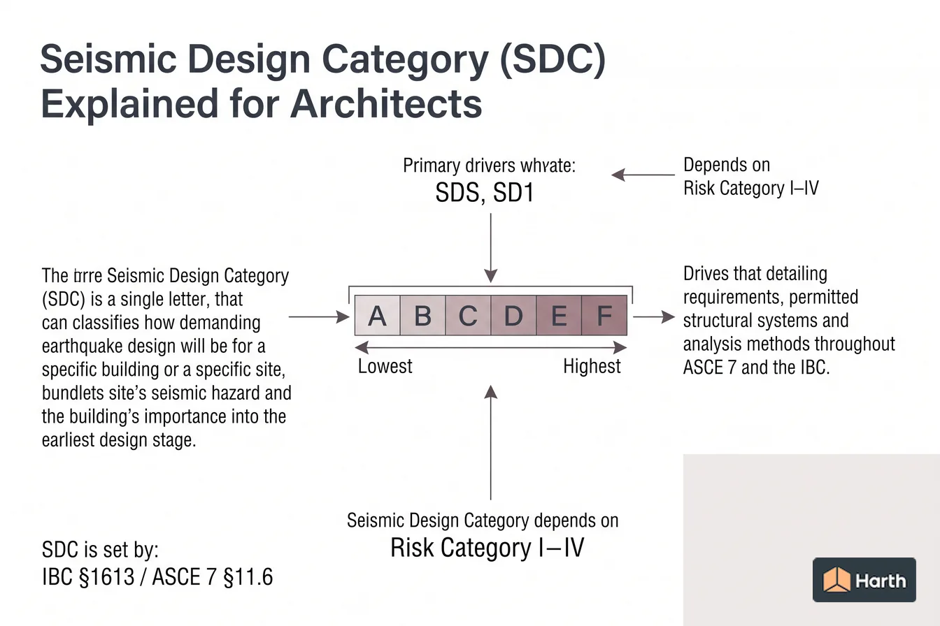
What the Seismic Design Category (A through F) is, what drives it, and why it shapes structural system choices, detailing, and cost from the earliest design stage. A key reference is primary drivers: SDS, SD1; check the cited source, edition, units, and applicability before using it for design, compliance, procurement, or approval. Range is A–F; A = lowest seismic demand, F = highest. Primary drivers is SDS, SD1; from Ss, S1, site class. Also depends on is Risk Category I–IV; occupancy/consequence. The Seismic Design Category (SDC) is a single letter, A through F, that classifies how demanding earthquake design will be for a specific building on a specific site. It bundles the site's seismic hazard and the building's importance into one label that then drives detailing requirements, permitted structural systems, and analysis methods throughout ASCE 7 and the IBC.
Content and cited inputs reviewed by Harth team · Published 2026-08-14 · Updated 2026-08-14.
What does this term mean?
Seismic Design Category (SDC) Explained for Architects: What the Seismic Design Category (A through F) is, what drives it, and why it shapes structural system choices, detailing, and cost from the earliest design stage.
What are the key takeaways?
- Range: A–F
- Primary drivers: SDS, SD1
- Also depends on: Risk Category I–IV
- Set by: IBC §1613 / ASCE 7 §11.6
Which site and code inputs control the design?
The Seismic Design Category (SDC) is a single letter, A through F, that classifies how demanding earthquake design will be for a specific building on a specific site. It bundles the site's seismic hazard and the building's importance into one label that then drives detailing requirements, permitted structural systems, and analysis methods throughout ASCE 7 and the IBC.
- SDC A / B — low seismic demand; minimal or standard detailing.
- SDC C — moderate demand; some system restrictions begin.
- SDC D — high demand; special detailing, common across much of the seismically active U.S.
- SDC E / F — very high demand, near active faults; most restrictive.
What drives it
| Input | Source | Role |
|---|---|---|
| Ss, S1 | USGS / ASCE Hazard Tool | Mapped short- and 1-second spectral accelerations |
| Site Class (A–F; nine classes in ASCE 7-22) | Geotechnical report | Soil amplification (Fa, Fv tables in ASCE 7-16; built into the ASCE 7-22 values) |
| SDS, SD1 | Calculated (ASCE 7-16) or read from the hazard tool (ASCE 7-22) | Design spectral accelerations |
| Risk Category (I–IV) | Occupancy | Consequence of failure |
The engineer computes SDS and SD1, enters ASCE 7 Tables 11.6-1 and 11.6-2 against the risk category, and takes the more severe result. Soft soils (Site Class D, E, F) amplify ground motion and can push a site up a category versus rock.
Seismic site class A–F and the ASCE 7-22 changes
Site class rates how the soil or rock in the top 100 ft (30 m) beneath the building amplifies shaking. The geotechnical engineer assigns it from the average shear-wave velocity, v̄s, over that depth. ASCE 7-22 Table 20.2-1 now has nine classes:
| Site class | Ground | Average shear-wave velocity v̄s (ft/s) |
|---|---|---|
| A | Hard rock | > 5,000 |
| B | Medium hard rock | > 3,000 to 5,000 |
| BC | Soft rock | > 2,100 to 3,000 |
| C | Very dense sand or hard clay | > 1,450 to 2,100 |
| CD | Dense sand or very stiff clay | > 1,000 to 1,450 |
| D | Medium dense sand or stiff clay | > 700 to 1,000 |
| DE | Loose sand or medium stiff clay | > 500 to 700 |
| E | Very loose sand or soft clay | 500 or less |
| F | Liquefiable, collapsible or highly organic soils; very thick soft clays | Site response analysis required (Section 20.2.1) |
More than 10 ft of soft clay (undrained shear strength below 500 psf, water content of 40% or more, PI above 20) makes a profile Site Class E whatever its v̄s. Velocity bands are as tabulated in FEMA P-2192-V1 Table 3-1 from ASCE 7-22.
What changed from ASCE 7-16 and the 2021 IBC:
- Three intermediate classes. BC, CD and DE were added to A–F to smooth the steps in site amplification.
- Velocity only. ASCE 7-16 also let SPT blow counts or undrained shear strength set the class directly; ASCE 7-22 uses v̄s alone, with SPT or CPT correlations allowed only to estimate it (checked at v̄s, v̄s/1.3 and 1.3v̄s, most critical result governs).
- Default site class. Where soils are not known, the 2021 IBC (Section 1613.2.2) uses Site Class D; ASCE 7-22 Section 20.1 uses the most critical of Site Classes C, CD and D, unless the AHJ or geotechnical data show DE, E or F.
- Rock needs proof. Site Class B requires shear-wave velocity measured on site; competent rock classified from geology alone is capped at BC. Classes A and B are not allowed where more than 10 ft of soil sits between the rock surface and the bottom of a spread footing or mat.
Reading the SDC from SDS and SD1
SS and S1 are the mapped risk-targeted maximum considered earthquake (MCER) spectral accelerations at 0.2 s and 1 s. Under ASCE 7-16 and the 2021 IBC they are adjusted by the site coefficients Fa and Fv to give SMS and SM1 (IBC Section 1613.2.3). ASCE 7-22 removed the Fa and Fv tables: the USGS data behind the ASCE Hazard Tool returns SMS, SM1, SDS and SD1 directly for the coordinates and site class entered. In each edition SDS = ⅔ SMS and SD1 = ⅔ SM1.
Look up each value against the risk category and keep the more severe letter:
| SDS (ASCE 7 Table 11.6-1) | SD1 (ASCE 7 Table 11.6-2) | Risk Cat. I, II or III | Risk Cat. IV |
|---|---|---|---|
| < 0.167g | < 0.067g | A | A |
| 0.167g to < 0.33g | 0.067g to < 0.133g | B | C |
| 0.33g to < 0.50g | 0.133g to < 0.20g | C | D |
| ≥ 0.50g | ≥ 0.20g | D | D |
The same breakpoints appear in 2021 IBC Tables 1613.2.5(1) and 1613.2.5(2) and in ASCE 7-22.
- E and F skip the tables. Where mapped S1 is 0.75g or more, Risk Category I–III buildings are SDC E and Risk Category IV buildings are SDC F.
- Low-hazard shortcut. Where S1 ≤ 0.04 and SS ≤ 0.15, the 2021 IBC (Section 1613.2.1) permits SDC A.
- SDS-only option. With S1 below 0.75, the SDS table alone may be used if the period, base-shear equation and diaphragm conditions of 2021 IBC Section 1613.2.5.1 are all met.
- Illustrative example. SDS = 0.40g with SD1 = 0.15g lands in SDC C for a Risk Category II office but SDC D for a Risk Category IV fire station on the same lot.
SDC maps. The 2024 IBC (Section 1613.2) adds SDC maps for default site conditions, Figures 1613.2(1)–(7), as an alternative to the ASCE 7 procedure. They may not be used where Site Class DE, E or F soils are present, and FEMA P-2192-4 notes they generally give the same or a higher SDC than ASCE 7 run with a specific site class. The IRC maps use SDS only and split D into D0, D1 and D2, with breakpoints at 0.17, 0.33, 0.50, 0.67, 0.83 and 1.25g.
Why it matters to architects
- Structural system — SDC D+ restricts or prohibits certain lateral systems and imposes height limits.
- Irregularities — plan and vertical irregularities carry penalties or are banned in higher SDCs, constraining massing and setbacks.
- Nonstructural anchorage — cladding, ceilings, and MEP need engineered seismic restraint as the SDC rises.
- Cost & schedule — special detailing and connections add both.
What changes from SDC A to SDC F
Nonstructural work is where architects feel the category most directly. Exemptions from ASCE 7-22 Chapter 13 (Table 13.1-1) shrink as the SDC rises:
| SDC | Components exempt from seismic design and bracing |
|---|---|
| A | All nonstructural components |
| B | Architectural components other than parapets where Ip = 1.0; all mechanical and electrical components |
| C | Mechanical and electrical components only where Ip = 1.0 and positively attached, or weighing 20 lb or less; architectural components are no longer exempt |
| D, E, F | Positively attached mechanical and electrical items of 400 lb or less with center of mass no more than 4 ft above the floor, flexible connections and Ip = 1.0; items of 20 lb or less; distribution systems at 5 lb/ft or less with Ip = 1.0 |
Furniture, temporary items in place 180 days or less and mobile equipment are exempt in every SDC. Egress stairways and fire sprinkler systems carry a component importance factor Ip of 1.5, so the Ip = 1.0 exemptions don't reach them.
On the structural side:
- Irregularities. Under ASCE 7-16 Section 12.3.3.1, an extreme weak story (Type 5b) is not permitted in SDC D, E or F; SDC E and F also prohibit extreme torsional irregularity (horizontal Type 1b), extreme soft story (vertical Type 1b) and weak story (Type 5a).
- System height limits. ASCE 7 Table 12.2-1 limits lateral systems by SDC; for example, a steel ordinary concentrically braced frame in a building frame system is limited to 35 ft in SDC D (FEMA P-2192-V1 worked example).
Get the authoritative value
Don't design to a remembered SDC. Enter the exact project address in the ASCE Hazard Tool (or the USGS Seismic Design Maps) to pull Ss and S1, pair them with the geotechnical site class, and let your structural engineer assign the SDC under the AHJ-adopted code edition.
Seismic Design Category & Site Class Explained (SDC A–F): structural-engineer handoff record
| Required input | Project entry |
|---|---|
| Site coordinates and jurisdiction | — |
| Adopted code / standard and edition | — |
| Risk category and occupancy basis | — |
| Official hazard-tool result and retrieval date | — |
| Site class, exposure, terrain or other relevant site input | — |
| Local amendments and authority confirmation | — |
| Engineer's derived design values | — |
| Engineer, checker and revision | — |
Stop condition: this page explains terminology and source workflow only. A generated diagram, map colour or generic example must not become a project design value.
Where can you explore related guidance?
- Explore all structural loads guidance
- Ground Snow Load (pg) Explained for Architects
- Design Wind Speed (Vult), Risk Category Maps & Exposure B/C/D
Sources and method
Concepts per ASCE 7 (Ch. 11) and IBC Section 1613; mapped acceleration parameters from the USGS Seismic Design Maps / ASCE Hazard Tool. Any values shown are illustrative and the official ASCE Hazard Tool + AHJ-adopted code govern. Official references: ASCE Hazard Tool; ASCE/SEI 7-22; 2024 IBC Chapter 16; 2021 IBC Chapter 16; FEMA P-2192-V1, 2020 NEHRP design examples; FEMA P-2192-4, SDC maps for 2024 IRC and IBC; UFC 3-301-01 nonstructural component design guide (ASCE 7-22); NCSEA ASCE 7-16 Irregularity Guide; USGS Design Ground Motions portal.
Source links
Frequently asked questions
Who assigns the Seismic Design Category?
The structural engineer of record determines the SDC, but it follows a defined procedure in ASCE 7 Section 11.6. You take the design spectral response accelerations SDS and SD1 (under ASCE 7-16 derived from the mapped Ss and S1 with site coefficients; under ASCE 7-22 returned directly by the hazard tool for the site class), look each up against the risk category in Tables 11.6-1 and 11.6-2, and assign the more severe of the two results. Where the mapped S1 is 0.75g or more, the building is assigned SDC E (Risk Category I–III) or F (Risk Category IV) regardless of the tables.
Why should an architect care about the SDC?
The SDC gates a large set of design decisions: whether special seismic detailing is required, which lateral force-resisting systems are permitted and their height limits, whether structural irregularities trigger penalties, and how nonstructural components (cladding, ceilings, partitions, MEP) must be anchored. A jump from SDC C to D can change the structural system, member sizes, and connection detailing — and therefore cost and architectural expression.
Does a higher risk category always raise the SDC?
Often, but not automatically. Risk Category IV buildings (essential facilities) face stricter SDC thresholds and can land in a higher category than a Risk Category II building on the same site. But on low-seismicity sites the SDC may stay at A or B regardless. Always confirm with the SDS/SD1 lookup rather than assuming.
What is seismic site class?
Seismic site class rates the ground in the top 100 ft under a building by how much it amplifies earthquake shaking. ASCE 7-22 assigns it from the average shear-wave velocity: Site Class A is hard rock above 5,000 ft/s, D is medium dense sand or stiff clay at 700–1,000 ft/s, and E is soft soil at 500 ft/s or less. Site Class F covers liquefiable or highly organic soils that need a site response analysis. The geotechnical report sets it.
What SDS value puts a building in Seismic Design Category D?
For Risk Category I, II or III buildings, SDC D applies where SDS is 0.50g or more, or SD1 is 0.20g or more (ASCE 7 Tables 11.6-1 and 11.6-2). For Risk Category IV the thresholds drop to SDS of 0.33g or SD1 of 0.133g. Whichever table gives the more severe category governs, and a mapped S1 of 0.75g or more moves the building to SDC E or F instead.
What does Seismic Design Category B require?
SDC B is low seismic demand: SDS from 0.167g up to 0.33g, or SD1 from 0.067g up to 0.133g, for Risk Category I–III buildings. For nonstructural work, ASCE 7-22 Table 13.1-1 exempts all mechanical and electrical components and any architectural component with an importance factor of 1.0, except parapets. Egress stairways carry an importance factor of 1.5, so they fall outside that exemption. Structural requirements still come from the engineer's ASCE 7 design.
Is there an IBC seismic design category map?
Yes, starting with the 2024 IBC. Section 1613.2 lets designers read the SDC from USGS-prepared maps for default site conditions (the most critical of Site Classes C, CD and D) instead of running the ASCE 7 procedure, but not where Site Class DE, E or F soils are present. The 2021 IBC maps show only SS and S1. The IRC also maps SDC directly, using SDS alone and splitting D into D0, D1 and D2.
Related pages
- Ground Snow Load (pg) Explained for Architects
Ground snow load explained for architects: how mapped pg values inform roof snow load and why location, elevation, exposure, and drift matter.
- Design Wind Speed (Vult), Risk Category Maps & Exposure B/C/D
Read design wind speed (Vult) from the right risk category map, then set Exposure B, C or D from upwind terrain using the ASCE 7 and IBC fetch rules.